Stamford generator manual. STAMFORD's Anti-Counterfeit Campaign. Verify your alternator. At NEWAGE ® STAMFORD ® AvK ®, we have been running an anti-counterfeit campaign since 2011 in order to protect our customers from the possibility of financial loss, safety and quality issues which are caused by counterfeit machines and spares. According to the World Trade Organization, the illegal counterfeit generator trade. Established in 1904, Cummins Generator Technologies manufactures alternators under the renowned NEWAGE ®, STAMFORD ® and AvK ® brands setting the industry standard, with a range extending from 7.5 to 11,200kVA, suitable for all generator set configurations. Although our products are used in a variety of applications, the common factor is that Cummins Generator Technologies work to a single.
- Express Pcb Gerber Files
- Pcb Gerber File Extensions
- How To Convert Gerber File To Pcb File In Altium
- How To Convert Gerber File To Pcb Files
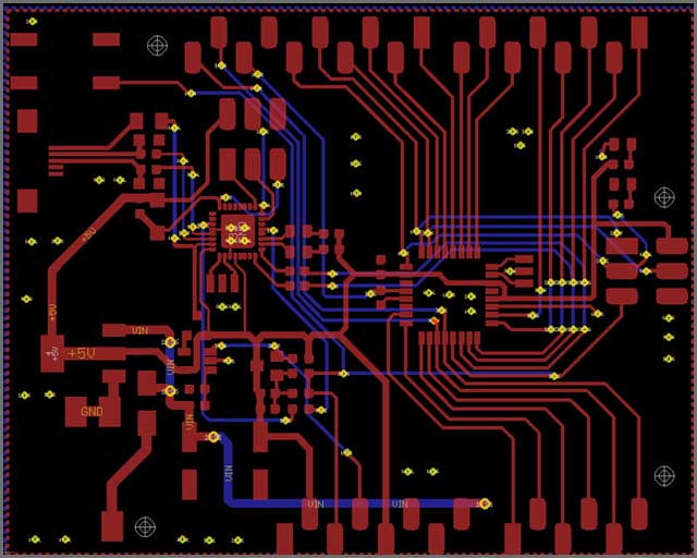
DesignSpark PCB provides a 'Manufacturing Plots' feature to allow you to produce Gerber files and use any board manufacturer you wish. Before producing the Gerber files ensure you have completed all the design checks of your PCB layout to ensure you do not have errors or unexpected cost penalties from selecting nonstandard track widths or spacing or other premium features. How To Convert PADs2005 to PCB Gerber File The file with PCB suffix can be opened by double-clicking the file directly and convert to PCB Gerber file Skip to content Mon - Fri: 9AM - 6PM Rm.1902, Easey Comm Bldg 253-261,Hennessy Road, Wanchai, HK 86-72.
EAGLE is a scriptable electronic design automation (EDA) application with schematic capture, printed circuit board (PCB) layout, auto-router and computer-aided manufacturing (CAM) features. EAGLE stands for Easily Applicable Graphical Layout Editor (German: Einfach Anzuwendender Grafischer Layout-Editor) and is developed by CadSoft Computer GmbH. The company was acquired by Autodesk Inc. in 2016.EAGLE contains a schematic editor, for designing circuit diagrams. Schematics are stored in files with .SCH extension, parts are defined in device libraries with .LBR extension. Parts can be placed on many sheets and connected together through ports.
The PCB layout editor stores board files with the extension .BRD. It allows back-annotation to the schematic and auto-routing to automatically connect traces based on the connections defined in the schematic.
When you finished your PCB design in Eagle, you could generate Gerber files which is needed by PCB manufacturer. This NextPCB’s article is telling you how to export the Gerber file from Eagle software.
Step 1.Open the CAM Processor
Open your PCB layout (.brd) file in Eagle, Click the “ CAM” button or choose “File -> CAM Processor”.This will open the CAM Processor tool that is used to generate the files.Step 2.Click File -> Open -> Job
Step 3.Then navigate to your default EAGLE cam folder, choose the GERBER_RS274x.cam file, press Open.
Step 4.Adding a second silk screen (Optional)
If you look at the Layer options, it doesn’t have a file for silk screen bottom.But if you need silk screen on bottom layer as well, follow these steps:a. Click “Add”
b. Change Section to something like “Silk Screen SOL”
c. Change File to “%N.pls”
d. Deselect all layers
e. Select layers 20 “Dimension”, 22 “bPlace” and 26 “bNames”
Step 5.Select the Process Job button to create all of your Gerber files.You can find all of your generated Gerber files in the Autodesk EAGLEControl Panel in your project folder.
Step 6.Generating Your Drill File
a. Select the CAM Processor at the top of your interface orselect File » CAM Processor to open the CAM processor dialog.
b. You now need to load a drill CAM job to get things started. Select File » Open » Job,
and in your default EAGLE cam folder select the excellon.cam file, then select Open.
c. you'll now have a single Generate drill data tab available, which will grab the data from layers 44 Drills and
45 Holes, just what you need. Select the Process Job button to generate this file.
After those step, Gerber files and Drill data have been exported from Eagle software.
Feel free to contact us: support@nextpcb.com
if you have any more questions.
Express Pcb Gerber Files
Once you've got your PCB layout finished and you're ready to start preparing for manufacturing, one of the critical steps is to generate Gerber files. These files are used by PCB manufacturers to prepare stencils for photoresist exposure and subsequent etching. When you're ready to create your Gerber files, you need the right set of CAM tools that can take data from your PCB layout. Altium Designer helps make the process for generating Gerber files quick and easy without forcing you to use an external program. In this article, we'll guide you through this process and show some example tasks you might need to perform to generate Gerber files.
What's in Your Gerber Files?
In an earlier post, we focused on creating a schematic for a simple active amplifier, then we created a simple 1-layer PCB layout from this schematic. The finalized layout is shown in the window below. We only have features in 2 layers on this board (1 silkscreen layer, 1 top PCB layer), as well as vias on some nets.
Finalized op-amp PCB layout with vias and silkscreen visible.

If we want to generate Gerber files for this PCB, we need to add a new OutJob file to the project. From here, you can create a host of deliverables for your PCB, including: Brick and lace songs free mp3 download.
- Gerber files in RS-274X and X2 formats
- Bills of materials in PDF or Excel format
- Fabrication drawings
- STEP files for importing your board into a mechanical design program
- Netlists (IPC-D-350 and IPC-D-356)
- DXF/DWG files for the PCB layout
- NC drill files
- Testpoint reports
- IPC-2581 and ODB++ output files
- Pick-and-place files for automated assembly
The image below shows the PCB layout above translated into Gerber files and viewed in the CAMtastic viewer. When you generate Gerber files, information in each layer will be saved in its own file, and these files can be loaded into a new CAMtastic document for inspection. The image below shows two layers from the above PCB layout. Here, only the silkscreen layer and copper features on the top layer are visible.
A preview of what our final PCB Gerber file will look like.
Note that there are additional files for other layers, which will be generated when you create your Gerber files. These other layers include more information than is shown in the above image. Although they aren't visible above, they include many important pieces of information:
- Pad locations for application of solder paste
- Drill hit locations, which are can be delineated by plated vs. non-plated through-holes
- Information in mechanical layers, such as a drill table, stackup diagram, and any dimensions
- Backdrill layer spans
- Soldermask openings
Some of these documents can be generated quite easily from an OutJob file in Altium Designer, while others require a few steps to setup. However, once you've setup the options in your OutJob file for your project, you can regenerate manufacturing deliverables whenever you want.
You can easily unlock iCloud account using an online method that requires you to download the iCloud unlocking software. One such method is by using the iCloud Remover software. The software functions by bypassing the iCloud activation lock and unlock iCloud lock. Unlock icloud service download.

How to Generate Gerber Files
To get started generating Gerber files, add a new OutJob file to your PCB project. Once this is created, you can start configuring which manufacturing files you need to generate, as well as the file formats you want. The image below shows an OutJob file with multiple options enabled for different sets of manufacturing documentation. An option has been created for Gerber RS-274X files and specificallt for backdrilled layers. To create a new export option for Gerber X2 files, right-click in the 'Fabrication Outputs' area and select the Gerber X2 entry.
Use an OutJob file to generate Gerber files.
Note that you can create multiple sets of Gerber outputs. In the above image, the 'Backdrill Gerbers' entry and the 'Gerber Files' entry are both in RS-274X format, but these options will generate Gerber files for different layer sets. After you create a new Gerber output option, you'll need to configure what information is exported with each of these options. The image below shows the dialog you'll use to select units, file format, and layers for export. To access this dialog, simply right-click on one of the Gerber file entries and click 'Configure.'
The above image shows the dialog you'll see for the RS-274X format, but you'll see a similar dialog if you want to export in the X2 format. There are two important tabs in this dialog:
- Layers Tab: You can scroll through the table on this tab and select specific layers for export. This includes all the electrical layers on your PCB, as well as mechanical layers, silkscreen layers, and any other layers in the PCB.
- Drill Drawing Tab: From here, you can select which paired drill layers will be converted to a Gerber file. By default, there is a 'Top layer-Bottom layer' option on this tab. However, if you've enabled any other unique via or drill features, like blind/buried vias or backdrilling, you will see options for these layer pairs as well.
In the image below, the Gerber files we want to export, as well as several other manufacturing files, have been enabled and will be exported to your local machine. Simply click 'Generate content' in the highlighted box on the right-hand side of this dialog.

You'll have a complete set of Gerber files and other deliverables once you click 'Generate content' in this dialog.
Pcb Gerber File Extensions
Now that you've created your Gerber files, you should inspect them to make sure there are no errors. Your Gerber files can reveal some simple problems that can cause a failed fabrication run. If you want to view your exported Gerber files, simply import them into a new CAMtastic document and scroll through each layer.
Another Way to Generate Gerber Files in Altium Designer
If you don't want to create an output job or you don't need to standardize your output format, you can skip this step and generate Gerber files from inside the PCB Editor. After saving you PCB layout, you can navigate to ‘File’ > ‘Fabrication Outputs’ > ‘Gerber Files.’ This will bring up the configuration window shown above. You can then select the layers you want to include in your exported Gerber file package, just like you would do with the OutJob file.
How To Convert Gerber File To Pcb File In Altium
You'll notice there are plenty of other fabrication and assembly file outputs that are accessible in the PCB Editor. With Altium Designer®, you can do much more than generate Gerber files. You'll have a complete set of CAD tools needed for PCB layout, routing, and fabrication/assembly drawing creation in a single program. Once you've finished creating your PCB layout and manufacturing files, you can easily share your data with your manufacturer using the Altium 365 platform.
How To Convert Gerber File To Pcb Files
We have only scratched the surface of what is possible to do with Altium Designer on Altium 365. You can check the product page for a more in-depth feature description or one of the On-Demand Webinars.
